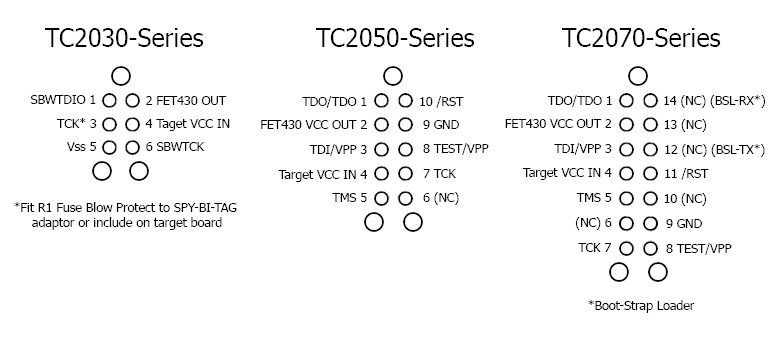
The TC2050-IDC-430 and TC2050-IDC-NL-430 are our 10-pin TC2050 cables fitted with a 14-pin ribbon connector to suit the FET430. Pin 10 of the TC2050 is connected to pin 11 of FET430, the extra 4 pins are not used or needed.
For the smallest footprint use the TC2050-IDC-NL “No Legs” version. It is designed to be held in place for programming but can also be held in place for debugging with our TC2050-CLIP board.
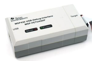
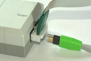
Take the ribbon connector end of the cable and plug it into the Target-end of the TI MSP430.
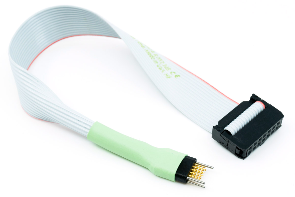
Tag-Connect's TC2050-IDC-430-NL programming cable is a special version of the TC2050-IDC-NL Plug-of-Nails™ cable designed to be plugged directly into TI's MSP-FET430 and is compatible with all MSP430 MCU's. The cable is fitted with a spring-pin Tag-Connector that conveniently plugs directly into your PCB and terminates in a 14-pin 0.1" ribbon connector that plugs directly into the FET430.
The cable is fitted with a spring-pin Tag-Connector.
Plugs straight to your PCB - No mating connector or header required!
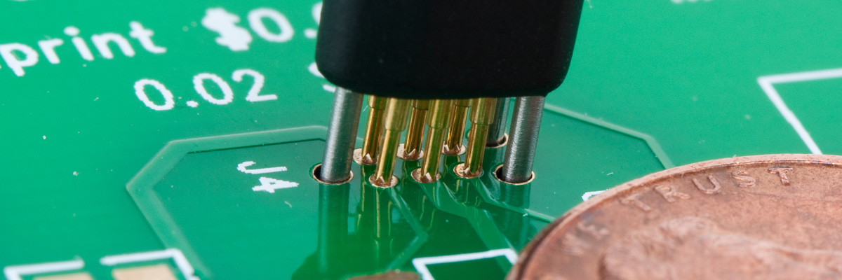
Requires only a tiny 0.03 square inch footprint of pads and locating holes in your PCB.
Footprint MUCH smaller than the standard 14-pin ribbon header.
Zero Cost Per Board!
High-Reliability Spring-Pins make a Secure Connection and are rated for over 100,000 operations.
Footprint has no height and reduces the size and space requirements of your PCB.
Can be retained in place using a TC2050-CLIP board.
Tag-Connect cables provide a simple, reliable means of connecting Debuggers and Programmers or other test equipment to your PCB's while lowering board costs and facilitating efficient production programming.
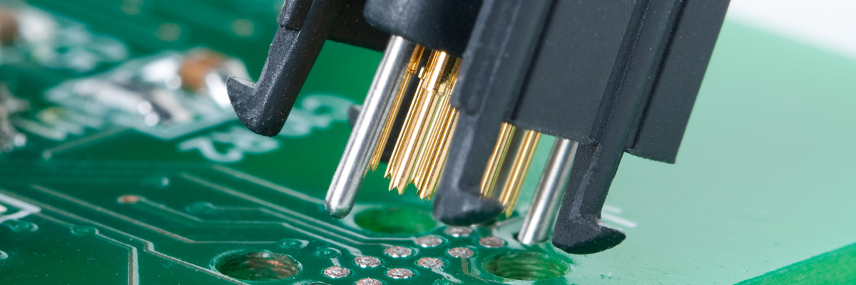
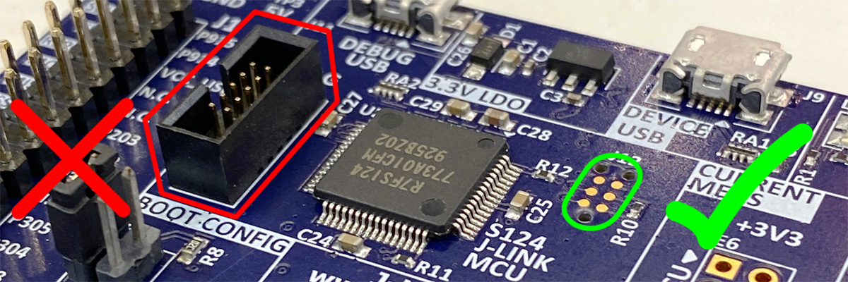
Tag-Connect uses a specially designed (Patent Pending) connector which eliminates the need for putting a programming header or other mating connector on every PCB. Instead, Tag-Connect uses tried and tested spring-pins rated for over 100,000 operations to make a secure connection to a special footprint pattern of pads and locating holes in your PCB.
The legged 'No Legs' footprint takes about the same board space as a couple of SMT resistors which means you can locate the footprint right next to the MCU if desired. If required, use the TC2050-CLIP board to secure the TC2050-IDC-430-NL connector to the PCB.
The 'No Legs' Tag-Connector is also compatible with the 'Legged' footprint, meaning you can conveniently debug with the self-retaining TC2050-IDC-430 and use TC2050-IDC-430-NL for a quick hand-held programming operation as may be typical during production.
This 10-conductor cable has a TC2050 Tag-Connector on one end and a standard 14-pin ribbon connector on the other and is wired specifically for the TI MSP-FET430 debugger (and compatible MSP430 debuggers). It is compatible with all MSP430 MCU's.
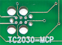
If your MSP430 device supports SPY-BI-WIRE, also take a look at the SPY-BI-TAG adaptor with the even smaller footprint (0.02 square inches) TC2030-MCP-NL 6-pin cables. This is the perfect solution where board space is premium!
Also available in self-retaining 'legged' version TC2050-IDC-430.
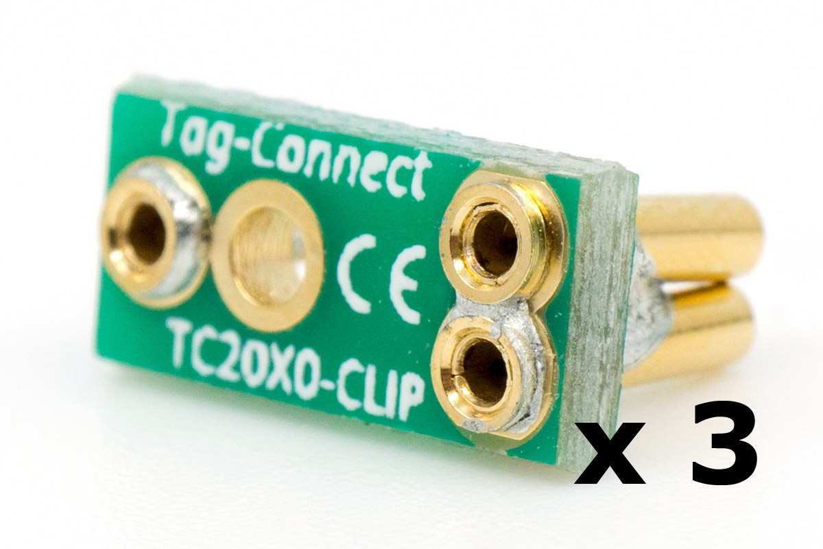
This product is intended to temporarily hold a TC2050-NL cable in place on a PCB. The solution will help when board space is premium and you need to perform a hands-free programming or debugging operation. For a more robust and convenient debugging connection consider using the TC2050 legged cable and footprint. Supplied as pack of 3.
We recommend keeping a few spare of these since they are easily misplaced when working on the desktop. Over time they may lose some grip.
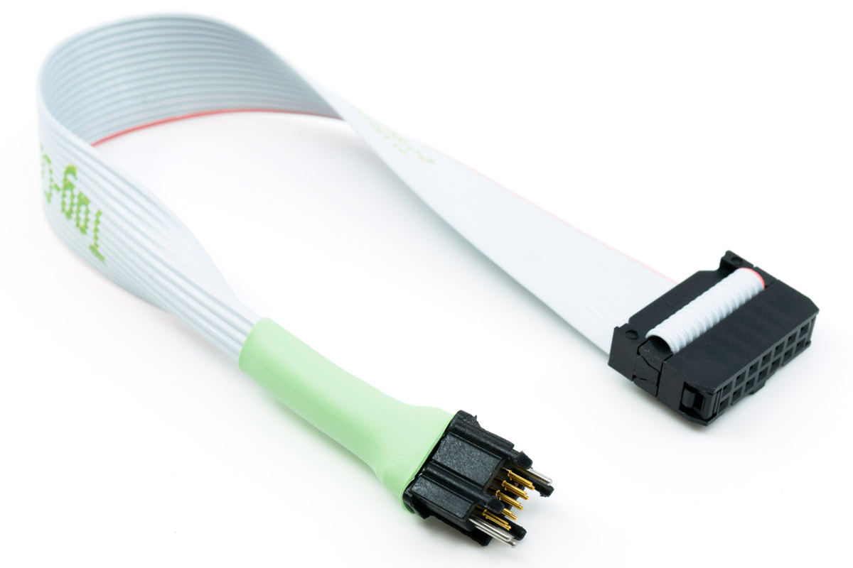
Tag-Connect's TC2050-IDC-430 programming cable is a special version of the TC2050-IDC Plug-of-Nails™ cable designed to be plugged directly into TI's MSP-FET430 and is compatible with all MSP430 MCU's.
The cable is fitted with a spring-pin Tag-Connector that conveniently plugs directly into your PCB and terminates in a 14-pin 0.1" ribbon connector.
Plugs straight to your PCB - No mating connector or header required!
Requires only a tiny footprint of pads and locating holes in your PCB.
Footprint MUCH smaller than the standard 14-pin ribbon header.
Zero Cost Per Board!
High-Reliability Spring-Pins make a Secure Connection and are rated for over 100,000 operations.
Footprint has no height and reduces the size and space requirements of your PCB.
Tag-Connect cables provide a simple, reliable means of connecting Debuggers and Programmers or other test equipment to your PCB's while lowering board costs and facilitating efficient production programming.
Tag-Connect uses a specially designed (Patent Pending) connector which eliminates the need for putting a programming header or other mating connector on every PCB. Instead, Tag-Connect uses tried and tested spring-pins rated for over 100,000 operations to make a secure connection to a special footprint pattern of pads and locating holes in your PCB.
The legged version footprint takes about the same board space as two or three SMT resistors which means you can locate the footprint right next to the MCU if desired.
This 10-conductor cable has a TC2050 Tag-Connector on one end and a standard 14-pin ribbon connector on the other and is wired specifically for the TI MSP-FET430 debugger (and compatible MSP430 debuggers). It is compatible with all MSP430 MCU's.
See also TC2050-IDC-NL-430 (no-legs version) with a tiny 0.03" footprint. Also, if your MSP430 device supports SPY-BI-WIRE, take a look at the SPY-BI-TAG adaptor with the even smaller footprint TC2030-MCP 6-pin cables.
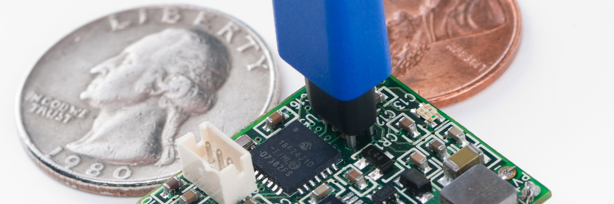
This is a fantastic solution if your implementation uses or can use SPY-BI-WIRE rather than the 4-wire JTAG. It reduces the PCB footprint to our smallest 6-pin TC2030 footprints and also allows you to use the more robust TC2030-MCP cables (far more robust than ribbon cables when used in production). Not only does it save the board space of the huge 14-pin connector, it also save you from having to put the 330 Ohm fuse-blow protection resistor on each and every target – just load it on the SPY-BI-TAG adapter instead!
For the smallest PCB footprint (using only about the same PCB space as an 0805 resistor) use the TC2030-MCP-NL “No Legs” cable with the SPY-BI-TAG adapter. For debugging it can be held in place with the TC2030-CLIP board. This also is an adavantage over the TC2050-IDC-430 4-wire JTAG solution as the extra spring-pin force of the TC2050 makes the TC2050-CLIP board harder to use than the TC2030.
We also offer a solution using our ECV3-06-MCP Edge-Connect™—a true edge-of-the-PCB connector. Edge-Connect™ is engineered to virtually eliminate the board space typically taken up by JTAG programming and test connectors. It’s the perfect choice for space-constrained PCBs and modules that don’t have room for traditional connectors but still need reliable access for firmware programming and testing.
Although SPY-BI-WIRE frees up the JTAG port allowing it to be used as GPIO, it is not quite as fast as the original 4-wire JTAG. However, unless your program is large (over 32K) you probably won’t notice any difference debugging and programming with SPY-BI-WIRE. If you have a larger device and use a lot of flash the download speed will suffer.
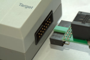
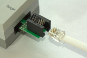
From the Target-end of the TI MSP430, connect your SPY-BI-TAG adaptor.
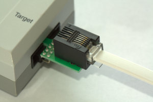
Plug the spring-pin end of the TC2030-MCP (-NL) to your target and you’re all set!
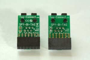
The SPY-BI-TAG adapter can be fitted with the 330 Ohm fuse-blow protection resistor. The best
(and safest) place for this resistor is on the adapter board, but some people (because they copy the confusing eval board schematics) put the 330 Ohm resistor on the target PCB. The resistor MUST be fitted either on the SPY-BI-TAG board, or on the target board but NOT both.
By default, R1 is not fitted (which is the safe thing because if it is also fitted on the target the fuse-blow current could cause damage). However visit the SPY-BI-TAG product page to order SPY-BI-TAG with the 330 Ohm 0805 resistor fitted.
Legs v. No-Legs: The legged version is more convenient but needs four extra holes for the feet. The TC2030-CLIP board pushes onto the three alignment pins of the “no legs” cable to retain it in place for debugging.
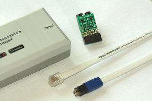
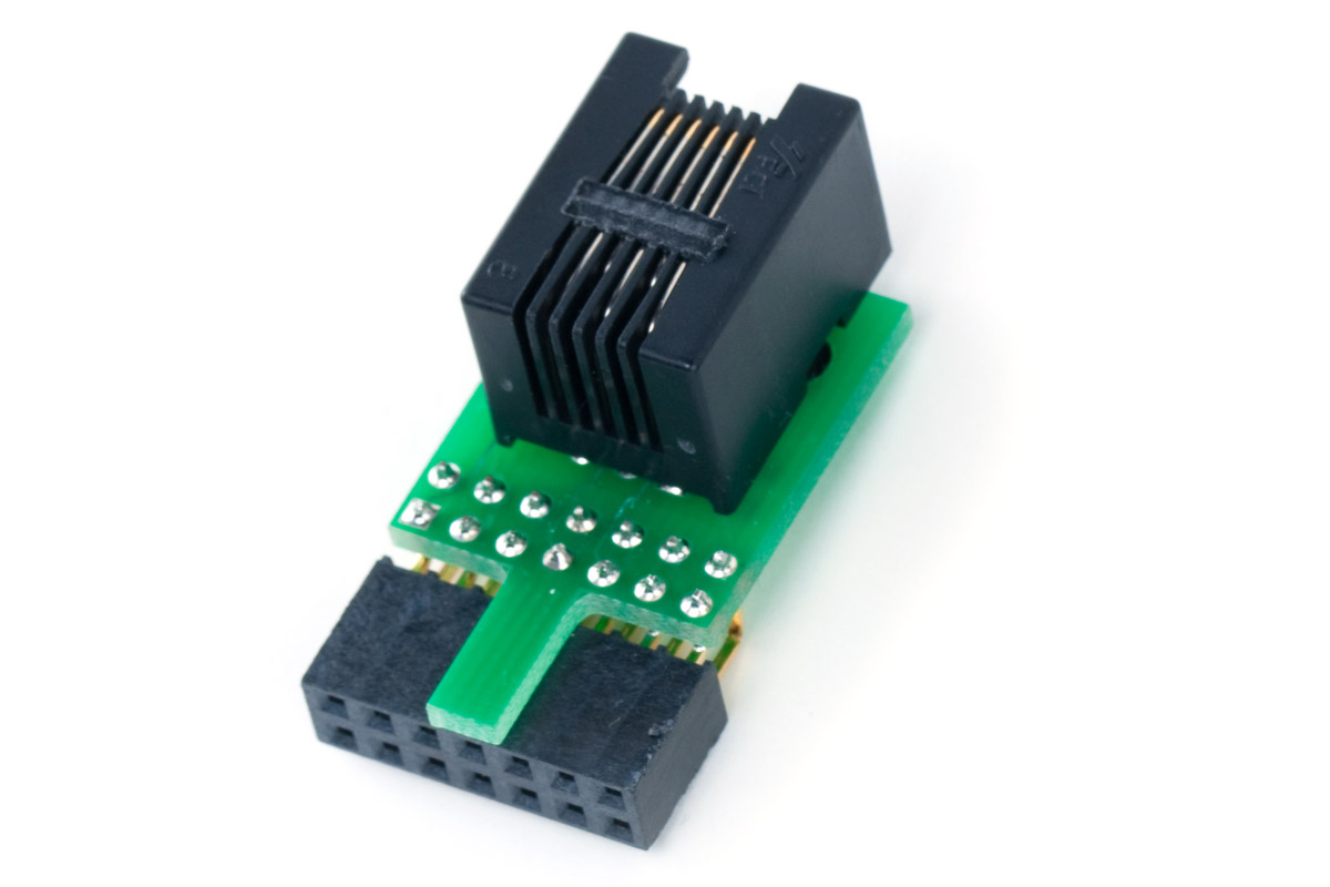
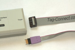
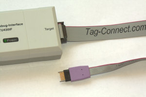
The “SPY‐BI‐TAG” TC2030‐MCP to SPY‐BI‐WIRE adapter board which allows use of our Tag‐Connect TC2030‐MCP series Plug‐of‐Nails™ cables with later versions of TI’s MSP430 MCU that support the SPY‐BI‐WIRE (2‐Wire) JTAG interface.
TI MSP‐FETU430 shown in one of the images with SPY‐BI‐TAG adapter board and TC2030‐MCP‐NL (no legs) cable – also works with TC2030‐MCP legged version cable. When your board real‐estate is at a premium, Tag‐Connect is the way to go!
The SPY-BI-TAG adapter can be fitted with the 330 Ohm fuse-blow protection resistor. The best (and safest) place for this resistor is on the adapter board, but some people (because they copy the confusing eval board schematics) put the 330 Ohm resistor on the target PCB. The resistor MUST be fitted either on the SPY-BI-TAG board, or on the target board but NOT both.
You can order this adapter with or without the 330 Ohm 0805 resistor fitted. Please select required option when ordering.
Note: Adapter only, MPS430, cable and evaluation board not included!
TC2030‐MCP to SPY‐BI‐WIRE adapter board which allows use of our Tag‐Connect TC2030‐MCP series Plug‐of‐Nails™ cables with later versions of TI’s MSP430 MCU that support the SPY‐BI‐WIRE (2‐Wire) JTAG interface.
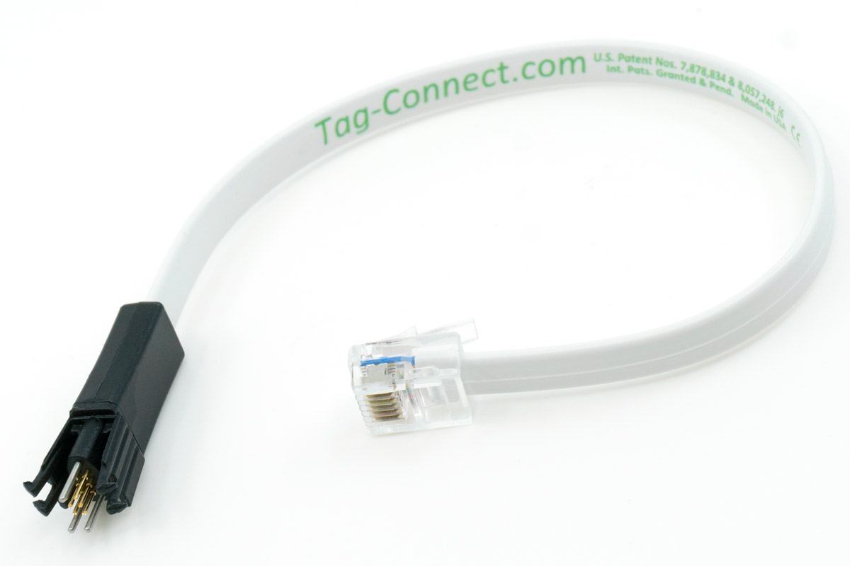
This special cable has a 6-pin ECV3-06 Edge-Connect™ connector and an RJ12 Modular Plug for Microchip ICD.
ECV3 is the third generation in the Edge-Connect™ family. ECV3 is NOT compatible with the previous Edge-Connect family and both will continue to be supported as current products into the future.
ECV3 makes some minor improvements adding greater robustness, improved convenience and is designed to be a mainstream product.
Edge-Connect™ is the patent-pending newest member in the family of Programming Connectors and Cables from Tag-Connect. ECV3-06 is the 6-pin connector.
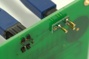
By connecting to the literal edge of the PCB (not the surface near the edge like traditional edge-connectors) Edge-Connect™ is designed to essentially eliminate the wasted real-estate needed by JTAG programming and test connectors.
Edge-Connect™ is an Ideal solution for space-sensitive PCB’s and modules that don’t have room on the board for traditional connectors but which still need a means of programming firmware and testing.
We've designed Edge-Connect™so that we can offer low-cost, fast-turn, customized connector solutions to meet the unique requirements of your PCB - Contact Us if you have a custom requirement.
Connects directly to the literal edge of the PCB
PCB snaps directly onto the Edge-Connect™
Zero Component Cost on the PCB
Maximizes available PCB real-estate
Eliminates the cost of a connector on every board
Requires just one tiny locating hole
Low profile edge access ideal for use with stacked PCB’s with no access headroom
Cant be connected backwards due to keyed feature
Standard or custom design configurations available
Alternative pitch? Three castellated edges? No problem!
No Header! - No Brainer!
Instead of using the usual space-costly Surface Mount or Plated Through-Hole connectors, Edge-Connect™ has springy gold-plated contacts that connect directly to the literal edge of the target PCB using edge castellation.
A Castellated PCB edge is a board edge that has plated through holes that are placed overhanging the edge of the board and typically made at little to no extra cost even from most cheap proto-board fab services (often a check box in the online quote is marked "Castellated Holes").
Castellated edges are commonly used on RF, WiFi, BLE and IoT sensor modules making them suitable for soldering as an SMT component onto host PCB’s using the castellated holes as pins. Edge-Connect™ allows test and programming and even debugging without first soldering the module to the host PCB. This makes it very useful for factory test and programming of the module.
ECV3-06-MCP has a castellation pitch of 1.27mm and requires a single tiny non-plated through hole to locate and hold the PCB in place.
New datasheet coming soon. Note that this product terminates in an RJ12 connector.
Note: ECV3-06-MCP with ribbon cable and RJ12 connector only supplied, Demo PCB not included.
The “SPY‐BI‐TAG” TC2030‐MCP to SPY‐BI‐WIRE adapter board which allows use of our Tag‐Connect TC2030‐MCP series Plug‐of‐Nails™ cables with later versions of TI’s MSP430 MCU that support the SPY‐BI‐WIRE (2‐Wire) JTAG interface.
TI MSP‐FETU430 shown in one of the images with SPY‐BI‐TAG adapter board and TC2030‐MCP‐NL (no legs) cable – also works with TC2030‐MCP legged version cable. When your board real‐estate is at a premium, Tag‐Connect is the way to go!
The SPY-BI-TAG adapter can be fitted with the 330 Ohm fuse-blow protection resistor. The best (and safest) place for this resistor is on the adapter board, but some people (because they copy the confusing eval board schematics) put the 330 Ohm resistor on the target PCB. The resistor MUST be fitted either on the SPY-BI-TAG board, or on the target board but NOT both.
You can order this adapter with or without the 330 Ohm 0805 resistor fitted. Please select required option when ordering.
Note: Adapter only, MPS430, cable and evaluation board not included!
TC2030‐MCP to SPY‐BI‐WIRE adapter board which allows use of our Tag‐Connect TC2030‐MCP series Plug‐of‐Nails™ cables with later versions of TI’s MSP430 MCU that support the SPY‐BI‐WIRE (2‐Wire) JTAG interface.
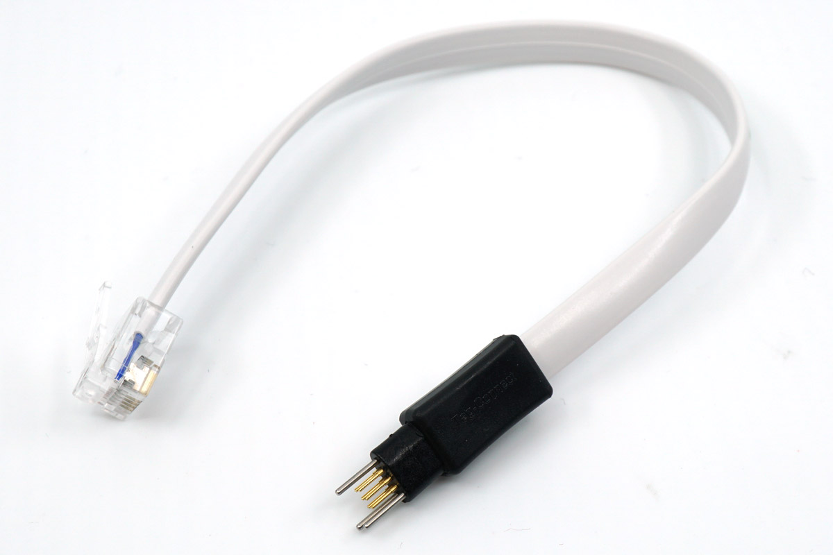
Tag-Connect TC2030-MCP-NL programming cable is primarily intended for use in production programming. It is particularly suited to environments where the connection to the PCB is of short duration, and operators are working quickly from board to board.
A major advantage of the TC2030-MCP-NL is the extremely small footprint required on the PCB (hardly any bigger than a surface mount resistor) allowing the minimum possible space on your PCB to be used for the programming connection.
The TC2030-MCP-NL is also compatible with the TC2030-MCP footprint allowing use of the TC2030-MCP for development work and TC2030-MCP-NL for fast programming in production.
The TC2030-MCP-NL can be held in place making it suitable for debugging and development when using TC2030-CLIP board .
Where a sustained connection to the PCB is required, also consider the TC2030-MCP.
Ideal for efficient production programming and also for debugging.
The “SPY‐BI‐TAG” TC2030‐MCP to SPY‐BI‐WIRE adapter board which allows use of our Tag‐Connect TC2030‐MCP series Plug‐of‐Nails™ cables with later versions of TI’s MSP430 MCU that support the SPY‐BI‐WIRE (2‐Wire) JTAG interface.
TI MSP‐FETU430 shown in one of the images with SPY‐BI‐TAG adapter board and TC2030‐MCP‐NL (no legs) cable – also works with TC2030‐MCP legged version cable. When your board real‐estate is at a premium, Tag‐Connect is the way to go!
The SPY-BI-TAG adapter can be fitted with the 330 Ohm fuse-blow protection resistor. The best (and safest) place for this resistor is on the adapter board, but some people (because they copy the confusing eval board schematics) put the 330 Ohm resistor on the target PCB. The resistor MUST be fitted either on the SPY-BI-TAG board, or on the target board but NOT both.
You can order this adapter with or without the 330 Ohm 0805 resistor fitted. Please select required option when ordering.
Note: Adapter only, MPS430, cable and evaluation board not included!
TC2030‐MCP to SPY‐BI‐WIRE adapter board which allows use of our Tag‐Connect TC2030‐MCP series Plug‐of‐Nails™ cables with later versions of TI’s MSP430 MCU that support the SPY‐BI‐WIRE (2‐Wire) JTAG interface.
Tag-Connect TC2030-MCP cable is primarily intended for use in development environments and is also ideal for production programming. The spring-loaded contact pins are held firmly in place by four plastic legs each of which clips securely into its own locating hole.
Tag-Connect TC2030-MCP is ideal where you need to maintain a connection to the PCB for an extended period such as when performing testing or development work.
See also TC2030-MCP-NL for applications where an even smaller footprint is required.
Ideal for both debugging and production programming.
Connect your TC2070-IDC or ECV3-14-2AP-IDC directly to your TI MSP430. The no-legs version can be held in place using the GRIP-14, but this setup isn’t recommended. The TC2070-IDC-NL has a strong spring force, which makes it hard to secure and unsuitable for frequent removal and reattachment.
Solutions
PCB connector
Debug Connector
Items (Click items for details)
Price
Qty
Buy
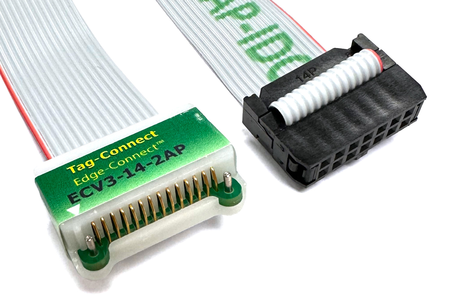
14 Pin to 14 Pin Edge-Connect™
PCB End: 14 Pin Edge-Connect™
Debug End: 14 Pin IDC 0.1" Female
Edge-Connect™ - The Leading-Edge Connector!
The ECV3-14-2AP-IDC is a 14-pin Edge-Connect™ connector terminated in a 14-pin 0.1″ pitch female IDC. This uses version 3 of our patented literal edge of the board connector which is more robust and more convenient. The 2AP version uses two guide pins.
ECV3 is the third generation in the Edge-Connect™ family. ECV3 is NOT compatible with the previous Edge-Connect family and both will continue to be supported as current products into the future.
ECV3 makes some minor improvements adding greater robustness, improved convenience and is designed to be a mainstream product.
Edge-Connect™ is the patented newest member in the family of Programming Connectors and Cables from Tag-Connect.
By connecting to the literal edge of the PCB (not the surface near the edge like traditional edge-connectors) Edge-Connect™ is designed to essentially eliminate the wasted real-estate needed by JTAG programming and test connectors.
Edge-Connect™ is an Ideal solution for space-sensitive PCB’s and modules that don’t have room on the board for traditional connectors but which still need a means of programming firmware and testing.
We've designed Edge-Connect™ so that we can offer low-cost, fast-turn, customized connector solutions to meet the unique requirements of your PCB - Contact Us if you have a custom requirement.
Connects directly to the literal edge of the PCB
PCB snaps directly onto the Edge-Connect™
Zero Component Cost on the PCB
Maximizes available PCB real-estate
Eliminates the cost of a connector on every board
Requires just two tiny locating holes
Low profile edge access ideal for use with stacked PCB’s with no access headroom
Cant be connected backwards due to keyed feature
Standard or custom design configurations available
Alternative pitch? Three castellated edges? No problem!
No Header! - No Brainer!
Instead of using the usual space-costly Surface Mount or Plated Through-Hole connectors, Edge-Connect™ has springy gold-plated contacts that connect directly to the literal edge of the target PCB using edge castellation.
A Castellated PCB edge is a board edge that has plated through holes that are placed overhanging the edge of the board and typically made at little to no extra cost even from most cheap proto-board fab services (often a check box in the online quote is marked "Castellated Holes").
Castellated edges are commonly used on RF, WiFi, BLE and IoT sensor modules making them suitable for soldering as an SMT component onto host PCB’s using the castellated holes as pins. Edge-Connect™ allows test and programming and even debugging without first soldering the module to the host PCB. This makes it very useful for factory test and programming of the module.
EC14-2AP-IDC has a castellation pitch of 1.27mm and requires two tiny non-plated through holes to locate and hold the PCB in place.
Note: ECV3-14-2AP-IDC with ribbon cable and IDC connector only supplied, Demo PCB not included.
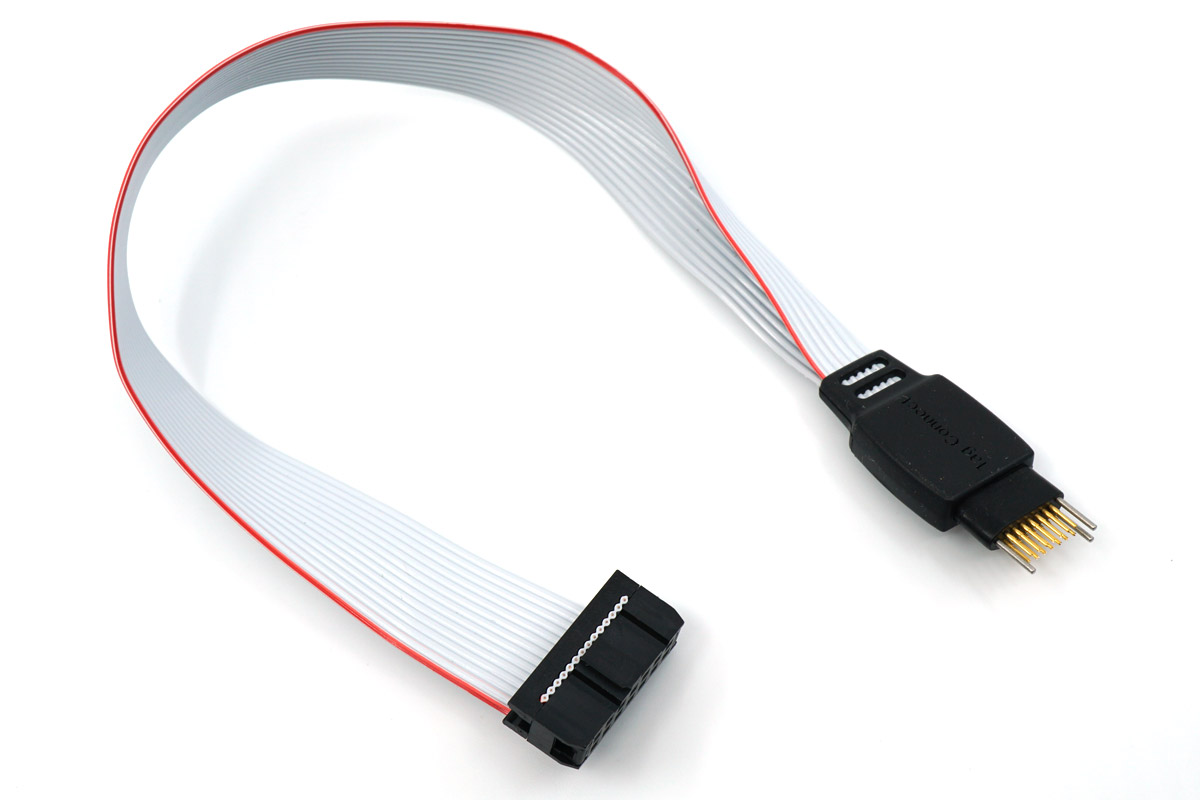
14-pin Plug-of-Nails™ programming/debug cable - No Legs Version
Fitted with 14-pin (2x7) 0.1" spaced ribbon cable connector.
Approx 8" (200mm) of ribbon cable between connectors.
See also TC2070-IDC (legged) version.
Note that for many applications where 14-pin connectors are natively used by a debugger (such as MSP430, TI and ADI DSP's, Renesas MCU's etc) we offer some excellent alternative solutions that in many cases can reduce the footprint size on your PCB to 6 or 10-pins as well as reducing the price per cable.
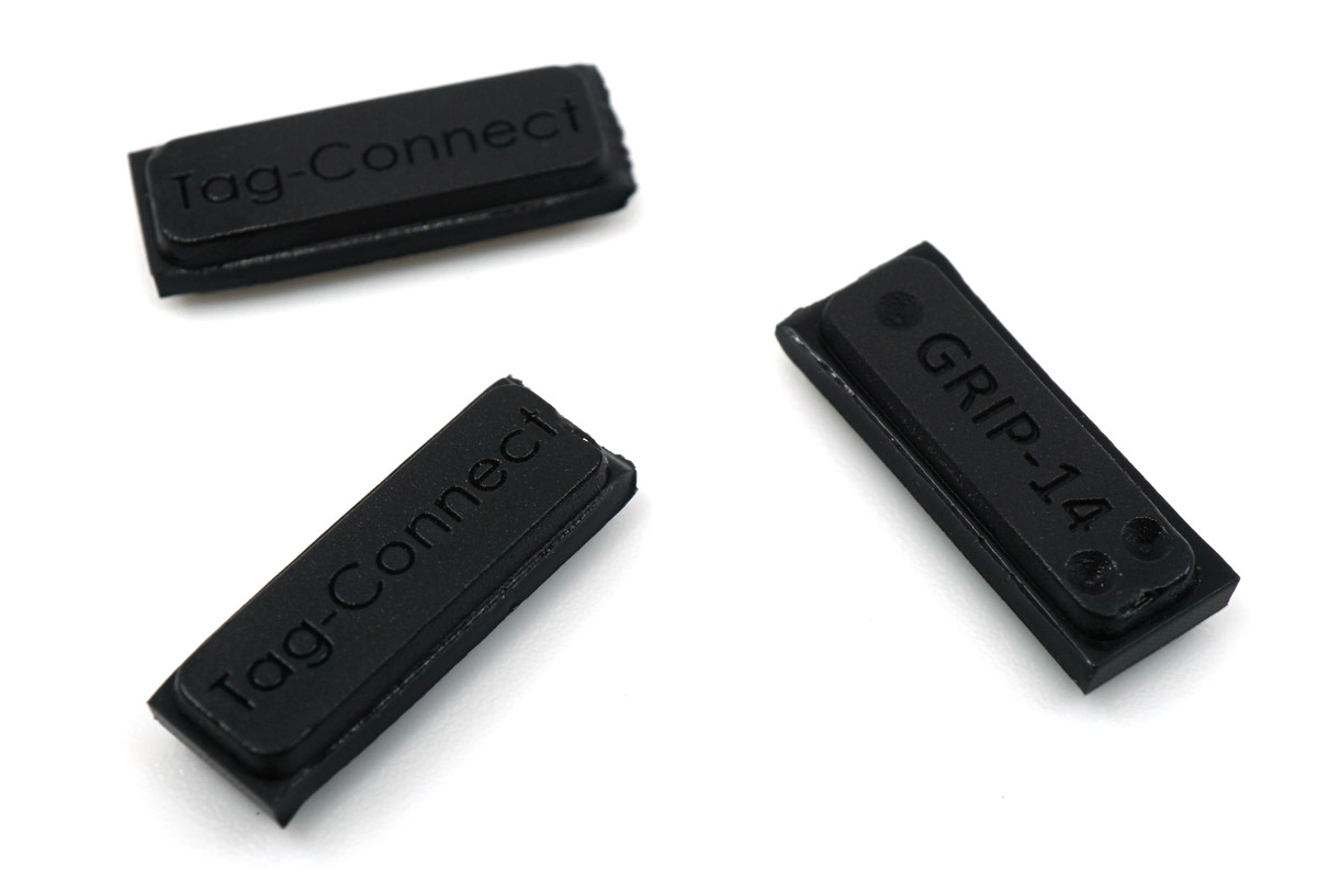
GRIP-14 is used to hold a TC2070 -NL cable to the PCB.
The GRIP presses onto the three alignment pins from underneath the PCB and grips tightly. It is non-conductive.
This is one pack, three in a pack.
Note on GRIP-14 Usage
The GRIP-14 is intended for semi-permanent attachment of a 14-pin NL cable (such as the TC2070-IDC-NL) to a PCB for debugging or development. Due to the strong spring force of the 14-pin NL connector, the GRIP-14 often struggles to hold the cable securely and may not work well. While some customers have used it successfully for long-term attachment, results vary, and in many cases the cable will pop off from the force of the 14 spring pins.
Installing the GRIP-14 requires firm pressure to push the alignment pins into the GRIP under the board. The safest method is to position the GRIP on a flat surface and press the connector straight down. Pressing with fingers alone can slip and may cause injury. The GRIP-14 is not designed for frequent insertions or removals.
We continue to offer it due to customer demand, but please be aware it may not provide a reliable connection in all situations. Contact us if you’d like help exploring alternative solutions.
14-pin Plug-of-Nails™ programming cable - With Legs Version
Fitted with 14-pin (2x7) 0.1" spaced ribbon cable connector.
Approx 8" (200mm) of ribbon cable between connectors.
Note that for many applications where 14-pin connectors are natively used by a debugger (such as MSP430, TI and ADI DSP's, Renesas MCU's etc) we offer some excellent alternative solutions that in many cases can reduce the footprint size on your PCB to 6 or 10-pins as well as reducing the price per cable.


 1 x SPY-BI-TAG: MSP430 SPY-BI-WIRE to TC2030-MCP Adapter Board
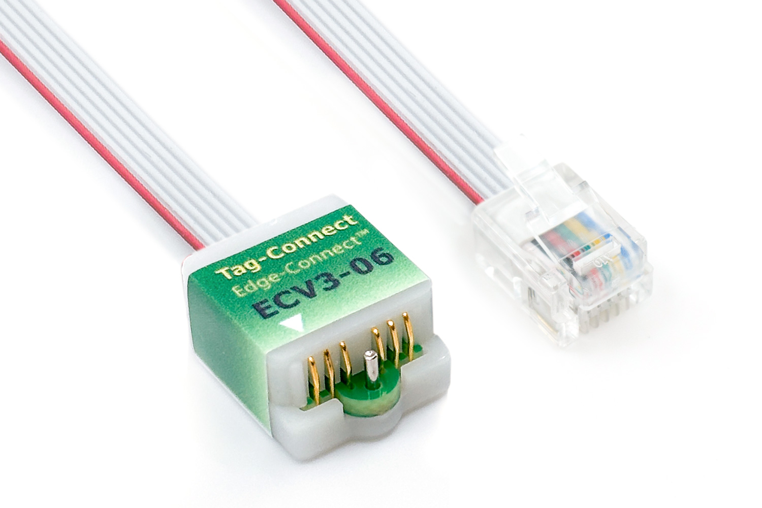
 1 x TC2070-IDC-NL
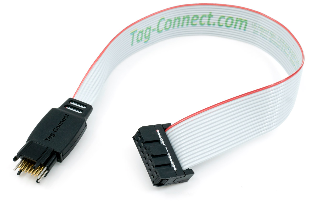 1 x TC2070-IDC